 helixoid
Life Sciences
Make the technology around your science work together.
Connect instruments, LIMS, ELN, scientific applications, and data platforms around the way your laboratory works.
The challenge
A result crosses more systems than anyone planned.
A result can cross several systems before a scientist can use it. Manual transfers, inconsistent identifiers, and missing context make that journey difficult to trace.
Implementation considerations
Make the boundaries explicit.
Start with the handoffs
Map how requests, samples, results, and exceptions move through the laboratory. Identify which system owns each record and where scientists have to reconcile information. The first integration should remove a specific source of friction.
Keep context with the result
A useful data flow preserves sample identifiers, method versions, timestamps, units, and processing history. Define those fields before building connectors so downstream applications can interpret the result correctly.
Design for interruptions
Instrument connections fail and source systems change. Plan for buffered capture, duplicate detection, controlled retries, and an operator review path. A dashboard should show which records need attention and who owns the next action.
Our approach to connected laboratories
Standardize physical access.
Make the instrument digitally addressable.
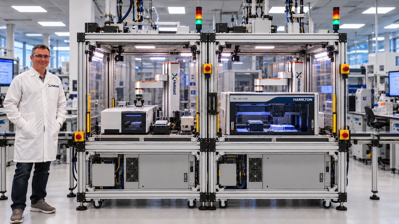
CAB and VIA connect the instrument’s physical integration to its representation in the laboratory’s orchestration fabric.
A consistent physical interface.
Define instrument placement, access, connections, and handoffs so integration requirements are explicit.
Explore Anatomy of CAB ↓VIA / Virtual Instrument AccessA usable digital representation.
Expose instrument capabilities, observed state, and result references through a reviewed software contract.
Explore VIA, why and how ↓Proposed Helixoid architecture. CAB and VIA describe the physical and digital access layers; the diagram does not establish deployed capability or an industry standard.
01 / Physical foundation
Anatomy of CAB
CAB means Configurable Automation Bench. It defines repeatable physical interfaces so instruments can join a configurable automation environment.
Standardize the way an instrument connects to the bench, while preserving the requirements that make that instrument work correctly.
CAB components
- 01
Signal tower
An external status indicator makes the concept workcell’s operating state visible.
- 02
Safety interlocks and light curtains
Access-monitoring and protection elements are shown at the enclosure boundary.
- 03
Plexiglass enclosure
Transparent panels surround the instrument and automation work zone.
- 04
Through-conveyor belt
The proposed rear pass-through connects adjoining instrument positions.
- 05
Aluminum extrusion frame
The 20 × 40 frame shown in the original concept provides the modular structure.
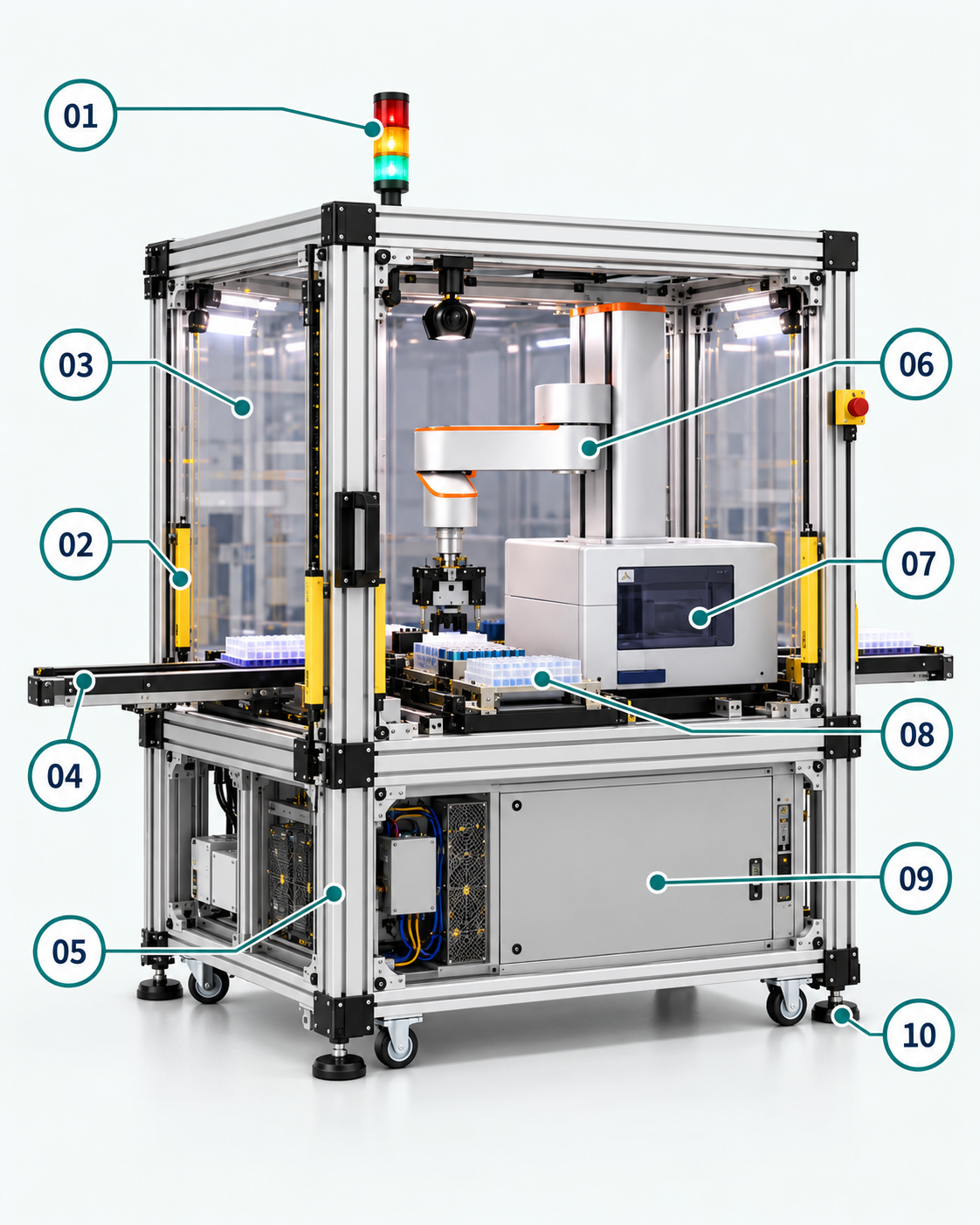
- 06
SCARA robot
A compact robot moves labware between the transfer position and the instrument.
- 07
Lab instrument
The hosted instrument retains its own operating, access, and maintenance requirements.
- 08
Labware and tools
Modular fixtures support the agreed carrier and material-handoff interface.
- 09
Control cabinet
The lower cabinet contains the PLC, local controls, and safety-control components shown in the study.
- 10
Leveling feet and casters
The base supports positioning and leveling as the physical layout is reconfigured.
A known place for each instrument.
Document mounting positions, reference points, access envelopes, and maintenance routes. The instrument’s working face and its automation access need clear, reviewable boundaries.
A consistent point of exchange.
Define the loading and unloading interface, carrier compatibility, and handoff ownership. A rear transfer path can connect adjoining modules where the chosen design supports it.
Connections with explicit requirements.
Document power, data, and any required utilities. Standard connection points make integration expectations visible; they do not make every instrument automatically compatible.
Keep physical authority at the bench.
Instrument controllers, access interlocks, limits, and safe-stop functions remain part of the physical integration. Orchestration requests work through the approved interface and cannot replace local safeguards.
02 / Digital instrument access
VIA, why and how
VIA means Virtual Instrument Access. It gives the orchestration fabric an addressable digital representation of instrument capabilities, state, and results.
Why VIA
A standard physical interface makes an instrument accessible. The digital layer also needs to know what it can do, whether it is available, what a request means, and how completion or failure will be reported.
How VIA works
A software adapter maps the instrument’s supported interface to a capability contract. VIA exposes that contract to orchestration and returns observed state, events, and result references with instrument identity and context.
- Identify
Describe the instrument.
Give the instrument a stable identity and a reviewed capability description, including availability and operating constraints.
- Connect
Map supported interfaces.
Use an adapter to translate approved requests and device feedback. Unsupported actions and ambiguous states need an explicit handling path.
- Coordinate
Join the orchestration fabric.
Let workflow software coordinate instrument availability and dependencies through a consistent access model, with permission checks and traceable records.
- Synchronize
Keep the representation current.
Feed observed status and results back into the digital representation. Define freshness and reconciliation rules so the model does not silently drift from the physical instrument.
From virtual access to a digital twin.
VIA provides the digital identity and access layer. A digital twin adds a defined model, appropriate validation, and maintained synchronization with the instrument. CAB establishes the physical interface; the adapter and state model make that interface usable digitally.
03 / One connected architecture
From CAB to VIA
to the orchestration fabric.
Authorized requests travel toward the instrument. Observed state, events, and result references travel back to the digital layer.
Scope the first step
Before the first commitment.
Do instruments have to be replaced to connect them?
Usually not. Most of this work sits in the capture and adapter layer between an instrument and the systems that record its output. Where an instrument exposes no usable interface, that limit is identified during the handoff review rather than assumed away.
Keep exploring
See how the pieces connect.
Our Approach
A proposed delivery lifecycle: how discovery, architecture, build, validation, and ongoing support follow from one another in an engagement.
Life SciencesScientific Data Platforms
Design scientific data foundations that preserve provenance, make information discoverable, and support analysis across research systems.
EngineeringTechnology & Integration Ecosystem
Explore integration categories and design considerations across laboratory systems, enterprise applications, cloud, data, and AI.
Start with one challenge
Let’s connect what comes next.
Bring the workflow, the systems, and the question. Define a useful next step together.